 The ATLAS activation studies
The ATLAS activation studies
The Muon Detector
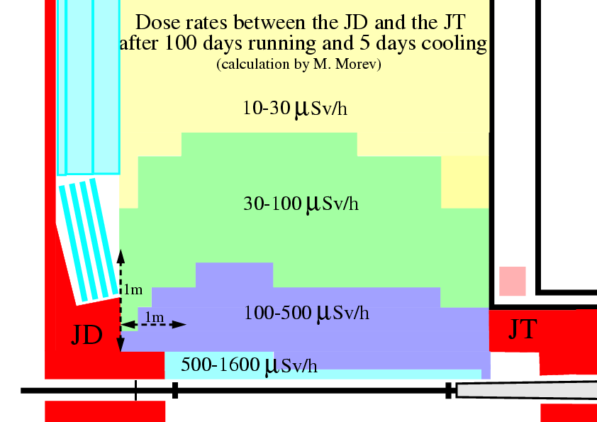
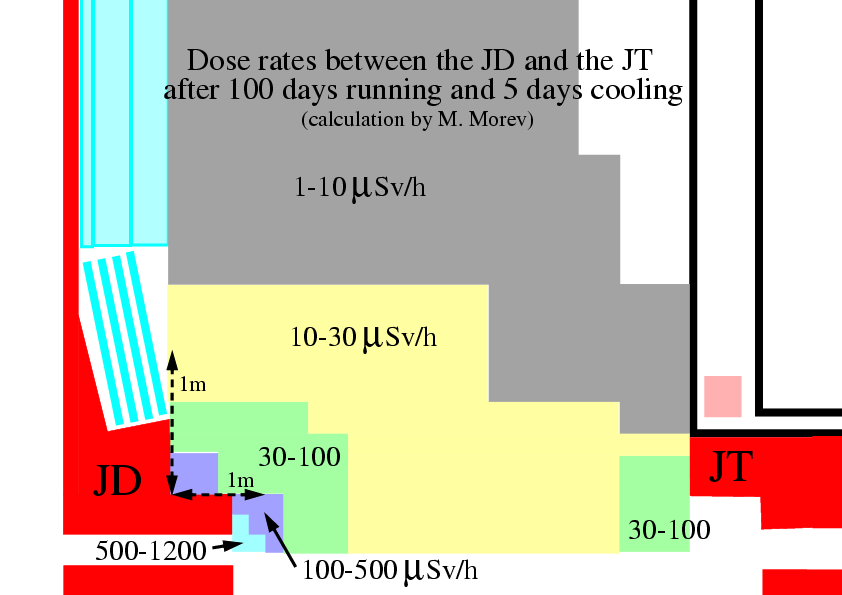
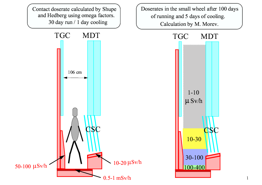
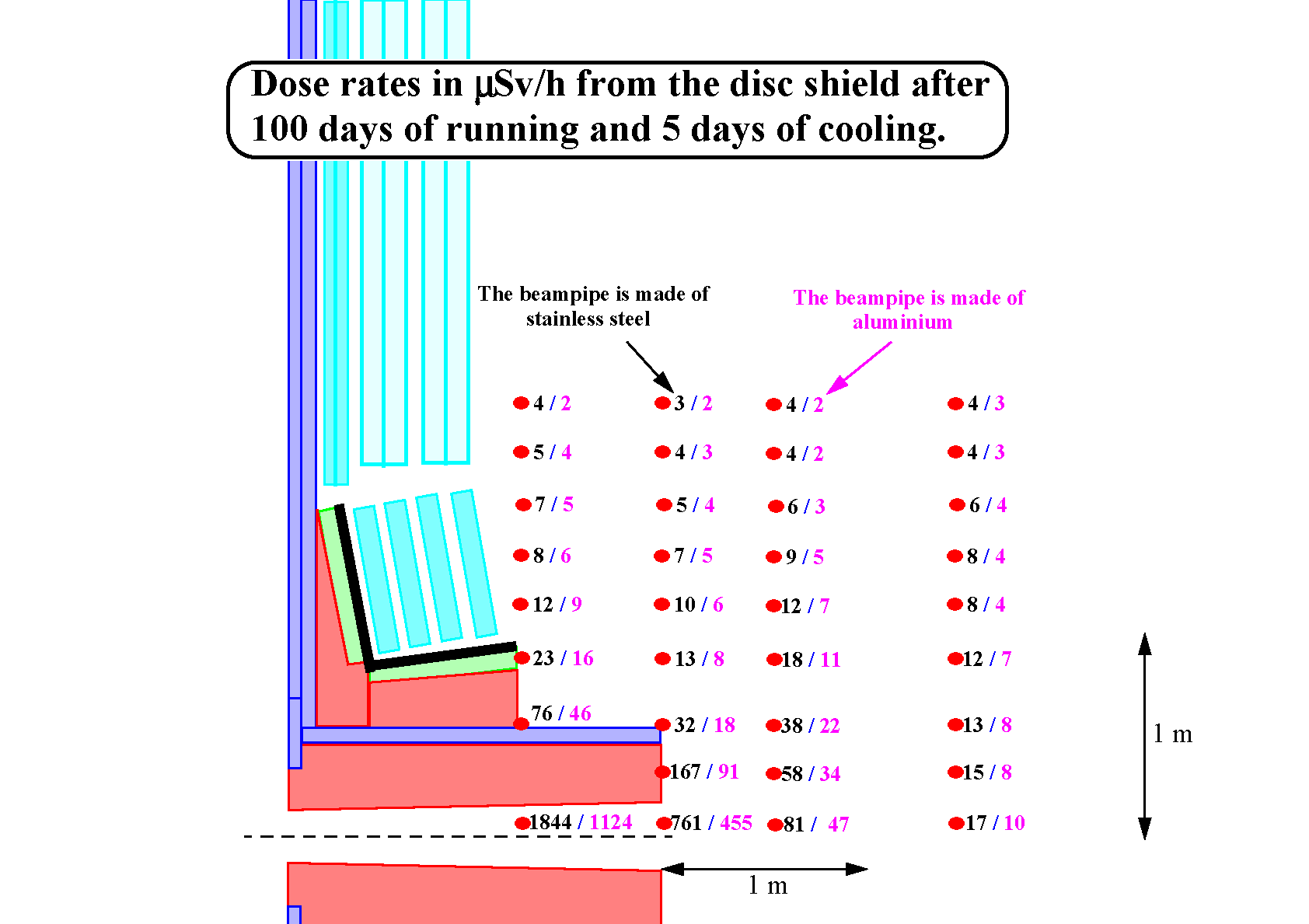
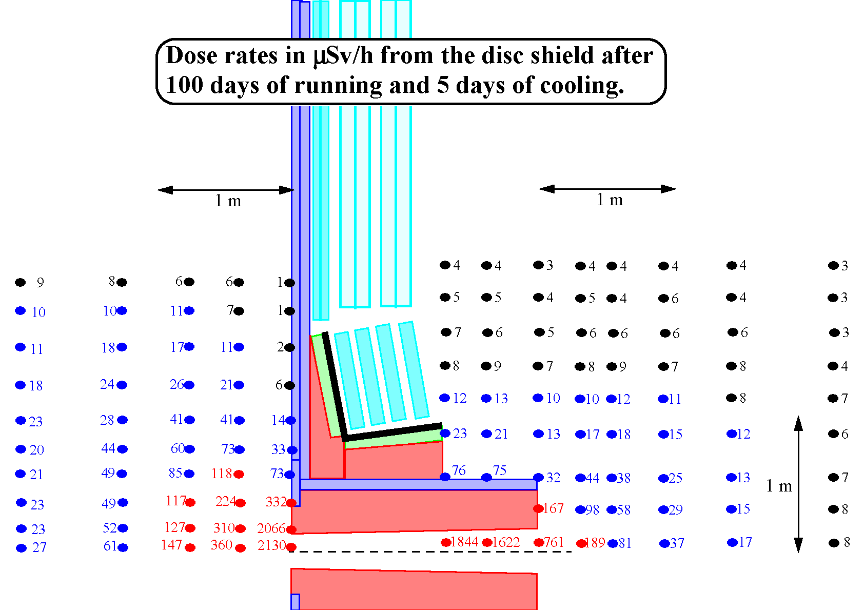
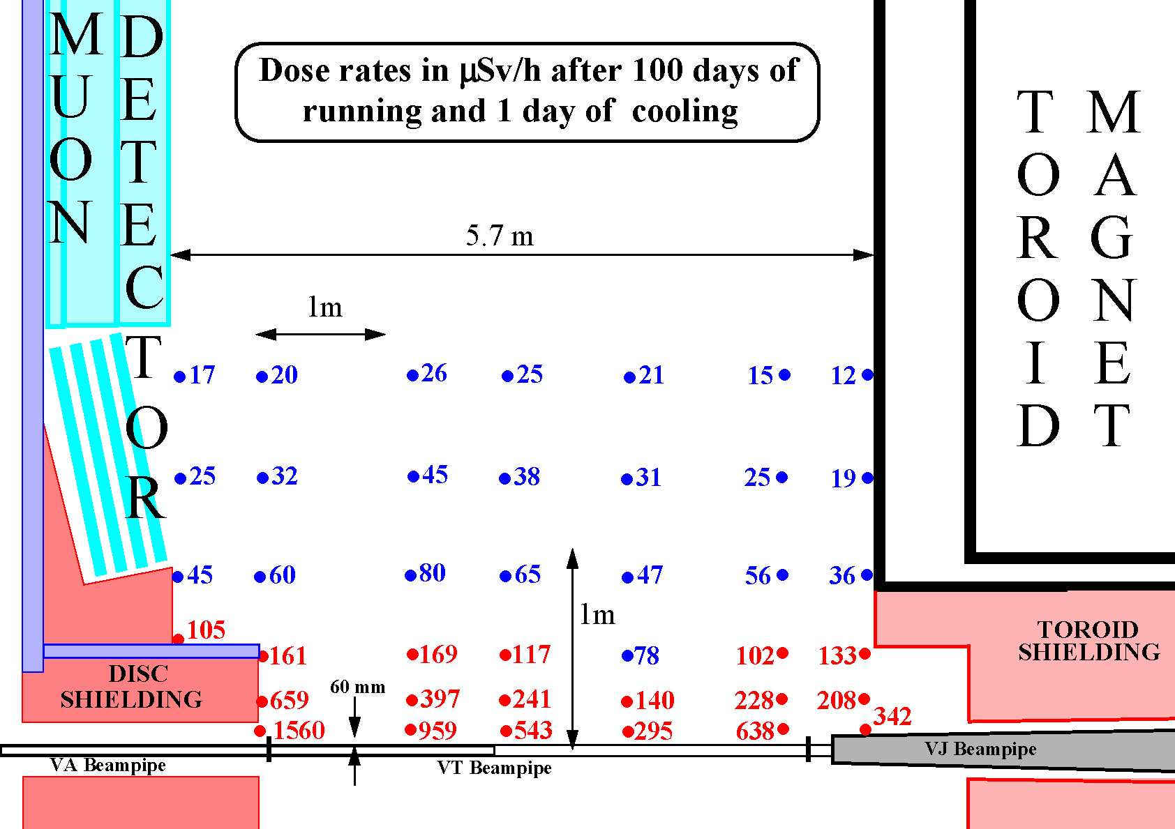
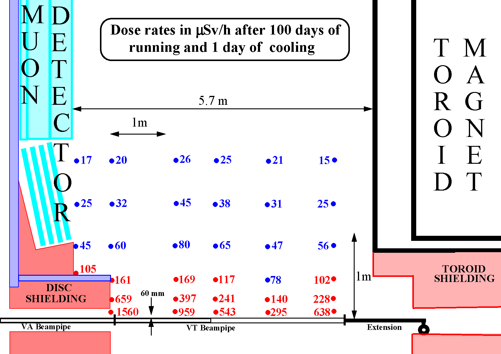
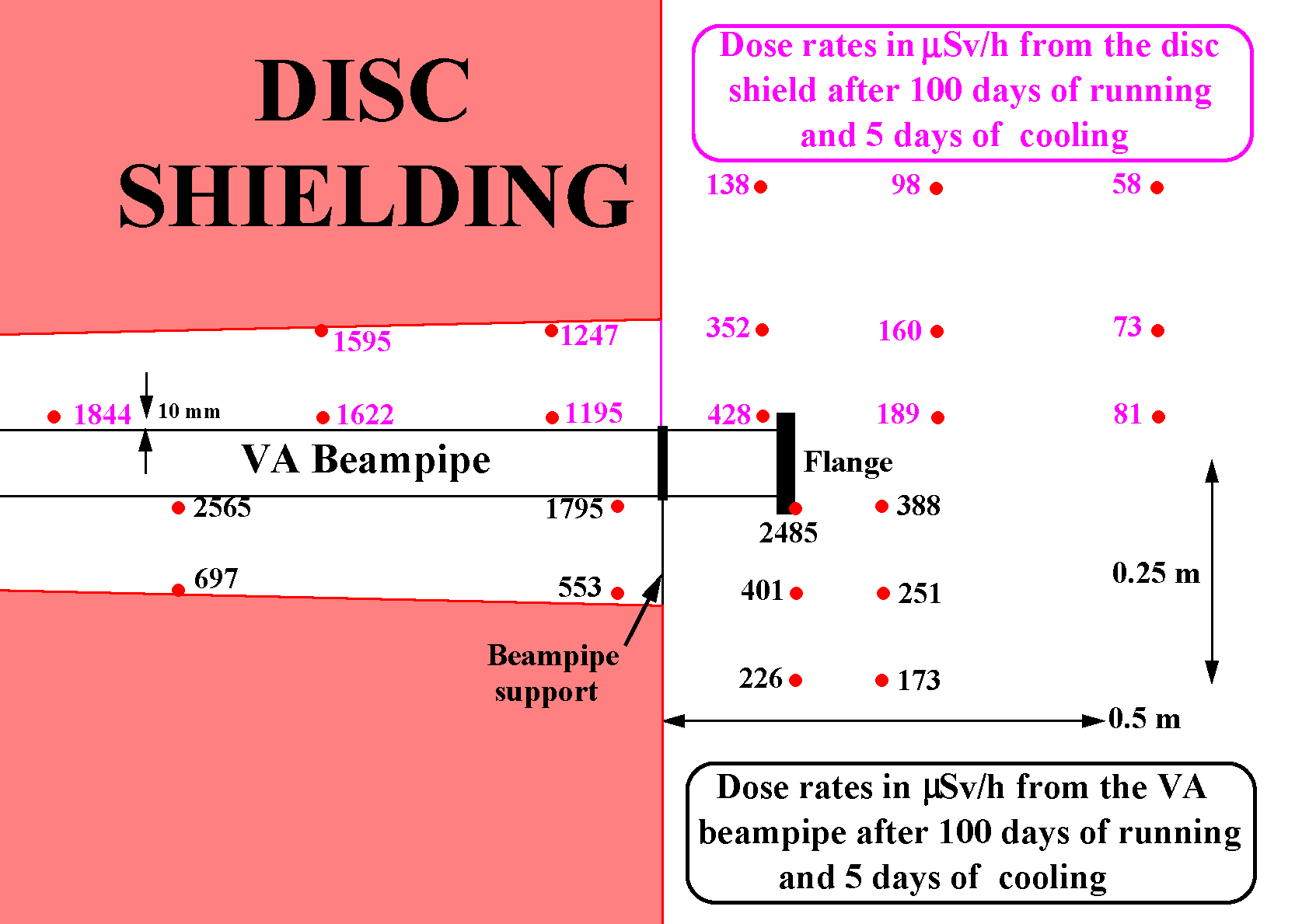
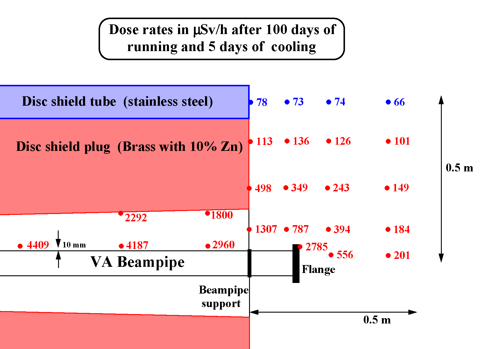
Plots by V. Hedberg from the above calculation:
Plots by V. Hedberg from the above calculation:
Plots by V. Hedberg from the above calculation:
Plots by V. Hedberg from the above calculation:
Back to the ATLAS home page
Responsible for the content of this page is
Vincent Hedberg
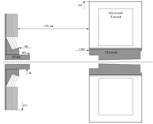
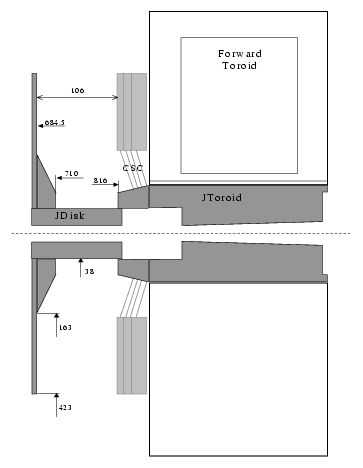
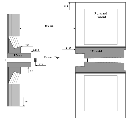
ACTIVATION DOSERATE IN ACCESS SCENARIOS TO THE AREA
BETWEEN DISK SHIELD AND TOROID
(the entire file in pdf-format)
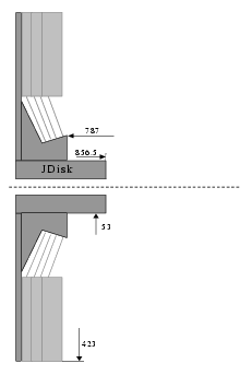
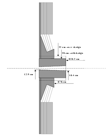
(Calculations using the old geometry of the JD)
(Calculations from fluxmaps with too large 10 cm binning)
(Calculations with the wrong geometrical description of the beampipe)
Report by V.A. Klimanov, E.I. Kulakova, M.N. Morev and V.K. Sakharov (October 2001)
ISTC Project #1800, 2nd quarter (Jul.-Sep. 2001)
(All files in PDF format)
Part 1: Text,
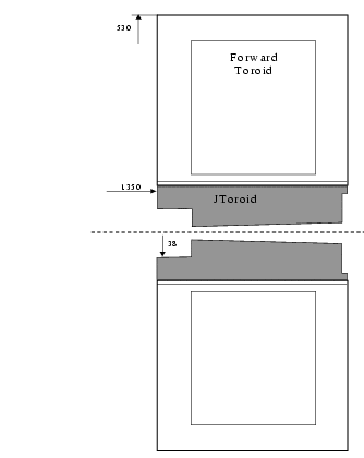
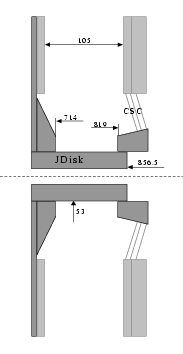
Table 1 - JD geometry and materials,
Table 2 - JT and toroid geometry and materials,
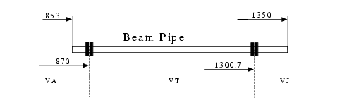
Table 3 - Beampipe geometry,
Table 4 - Material Composition
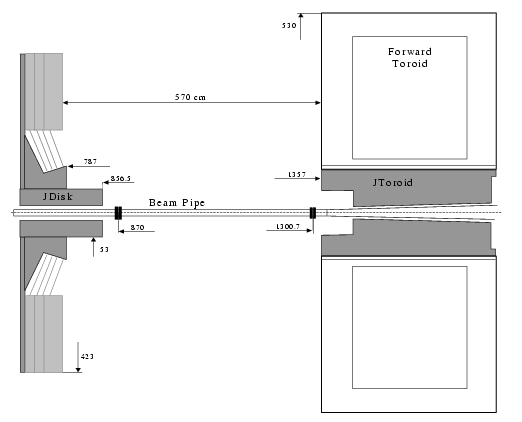
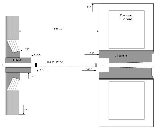
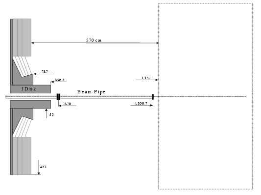
Part 2: Table 5 - Total doserates between the JD and the JT with the beampipe installed
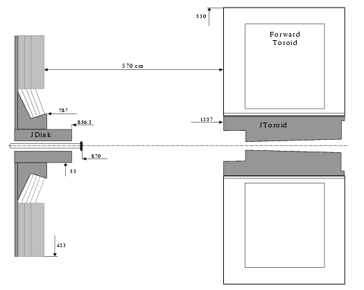
Part 3: Table 6 - Total doserates between the JD and the JT with the beampipe removed
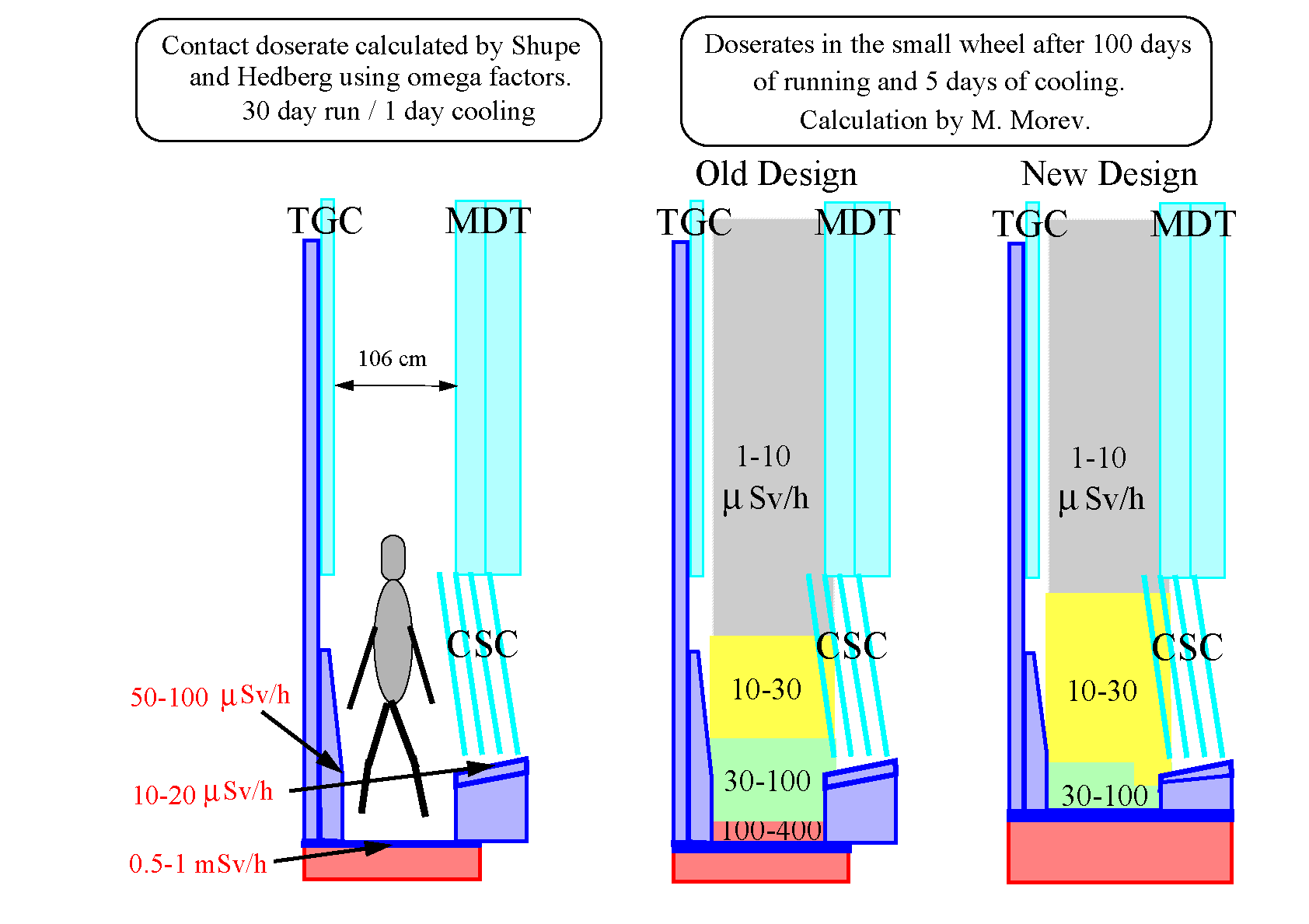
Part 4: Table 7-8 - Doserates during access to the small wheel
Part 5:
Table 9-10 - Doserates from the JD
Table 11-12 - Doserates from the JT
Table 13-14 - Doserates from the beampipe
Table 15 - Comparison between the DOT and MCNP programs

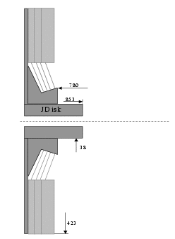
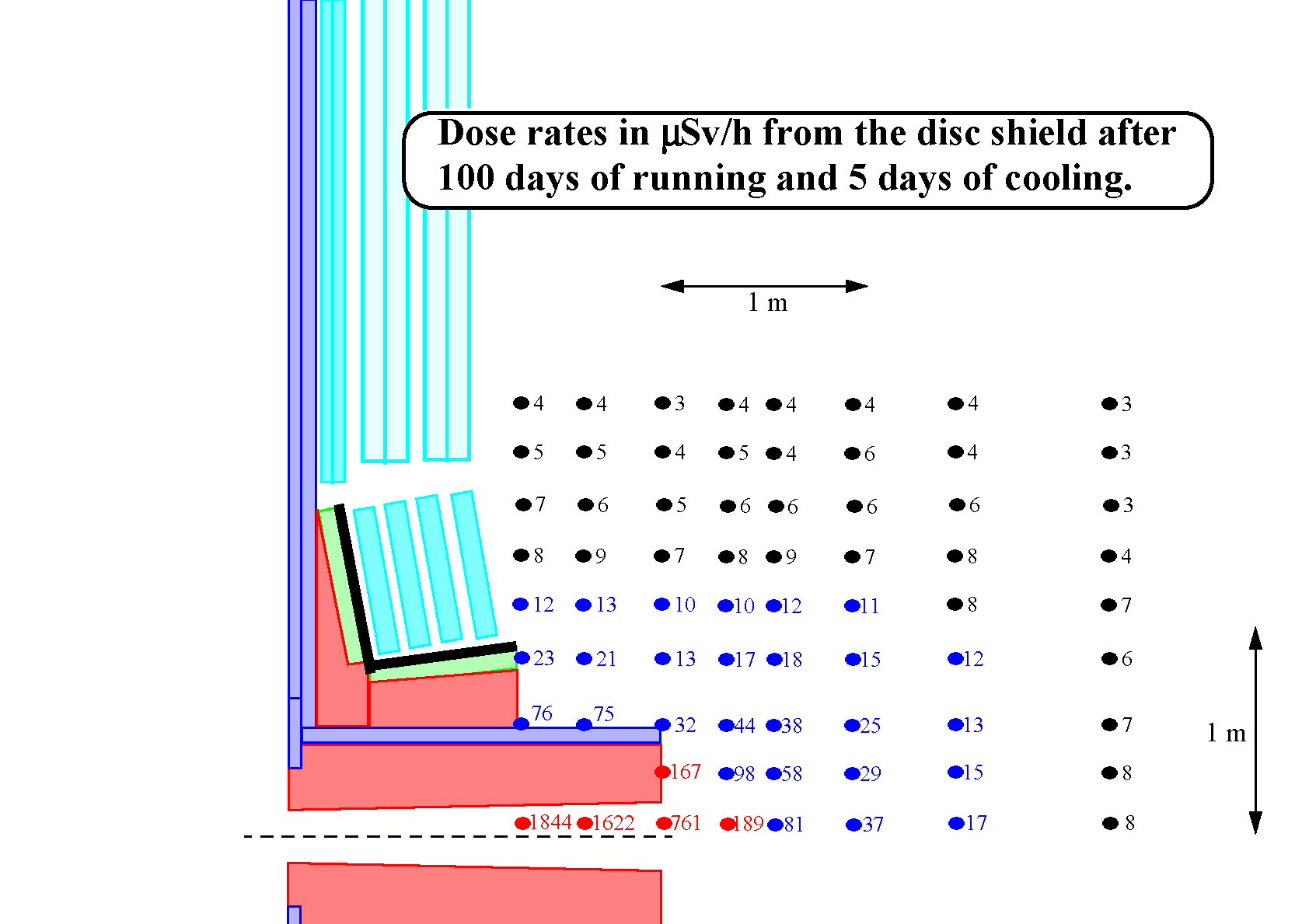
DOSE RATES BEHIND THE JD
(file in pdf-format)
Report by M.N. Morev (August 2002)
ACTIVATION DOSERATE IN THE ACCESS REGION INSIDE THE SMALL WHEEL
(the entire file in pdf-format)
Report by M.N. Morev (August 2002)
Part 1: Calculation with all trace elements
Part 2: Calculation without Sb in the lead and without Co in the stainless steel
DOSE RATES BETWEEN THE JD AND THE JT WITH BEAMPIPE
(file in pdf-format)
Report by M.N. Morev (August 2002)


Back to the activation page.